
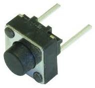
Pushbuttons or switches connect two open terminals in a circuit. This
example turns on the LED on pin 2 when you press the pushbutton switch
connected to pin 8.
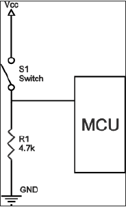
An example of a pull-down resistor in a digital circuit is shown in the following figure. A pushbutton switch is connected between the supply voltage and a microcontroller pin. In such a circuit, when the switch is closed, the micro-controller input is at a logical high value, but when the switch is open, the pull-down resistor pulls the input voltage down to the ground (logical zero value), preventing an undefined state at the input.
The pull-down resistor must have a larger resistance than the impedance of the logic circuit, or else it might pull the voltage down too much and the input voltage at the pin would remain at a constant logical low value, regardless of the switch position.

Pull-down Resistor
Pull-down resistors are used in electronic logic circuits to ensure that inputs to Arduino settle at expected logic levels if external devices are disconnected or are at high-impedance. As nothing is connected to an input pin, it does not mean that it is a logical zero. Pull down resistors are connected between the ground and the appropriate pin on the device.An example of a pull-down resistor in a digital circuit is shown in the following figure. A pushbutton switch is connected between the supply voltage and a microcontroller pin. In such a circuit, when the switch is closed, the micro-controller input is at a logical high value, but when the switch is open, the pull-down resistor pulls the input voltage down to the ground (logical zero value), preventing an undefined state at the input.
The pull-down resistor must have a larger resistance than the impedance of the logic circuit, or else it might pull the voltage down too much and the input voltage at the pin would remain at a constant logical low value, regardless of the switch position.
Components Required
You will need the following components −- 1 × Arduino UNO board
- 1 × 330 ohm resistor
- 1 × 4.7K ohm resistor (pull down)
- 1 × LED
Procedure
Follow the circuit diagram and make the connections as shown in the image given below.
Sketch
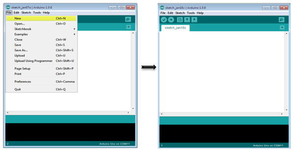
Open the Arduino IDE software on your computer. Coding in the Arduino language will control your circuit. Open a new sketch File by clicking on New.
Arduino Code
// constants won't change. They're used here to
// set pin numbers:
const int buttonPin = 8; // the number of the pushbutton pin
const int ledPin = 2; // the number of the LED pin
// variables will change:
int buttonState = 0; // variable for reading the pushbutton status

void setup() {
   // initialize the LED pin as an output:
   pinMode(ledPin, OUTPUT);
   // initialize the pushbutton pin as an input:
   pinMode(buttonPin, INPUT);
}

void loop() {
   // read the state of the pushbutton value:
   buttonState = digitalRead(buttonPin);
   // check if the pushbutton is pressed.
   // if it is, the buttonState is HIGH:
   if (buttonState == HIGH) {
      // turn LED on:
      digitalWrite(ledPin, HIGH);
   } else {
      // turn LED off:
      digitalWrite(ledPin, LOW);
   }
}
No comments:
Post a Comment