
To render 3D graphics, we have to follow a sequence of steps. These steps are known as graphics pipeline or rendering pipeline. The following diagram depicts WebGL graphics pipeline.
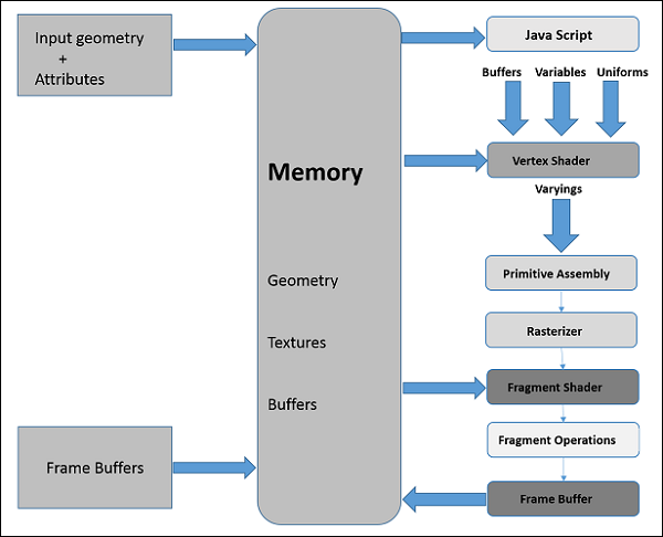 In the following sections, we will discuss one by one the role of each step in the pipeline.
Some fragment operations are carried out after determining the color of each pixel in the primitive. These fragment operations may include the following −
In the following sections, we will discuss one by one the role of each step in the pipeline.JavaScript
While developing WebGL applications, we write Shader language code to communicate with the GPU. JavaScript is used to write the control code of the program, which includes the following actions −- Initialize WebGL − JavaScript is used to initialize the WebGL context.
- Create arrays − We create JavaScript arrays to hold the data of the geometry.
- Buffer objects − We create buffer objects (vertex and index) by passing the arrays as parameters.
- Shaders − We create, compile, and link the shaders using JavaScript.
- Attributes − We can create attributes, enable them, and associate them with buffer objects using JavaScript.
- Uniforms − We can also associate the uniforms using JavaScript.
- Transformation matrix − Using JavaScript, we can create transformation matrix.
Vertex Shader
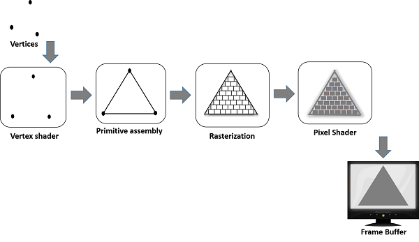
When we start the rendering process by invoking the methods drawElements() and drawArray(), the vertex shader is executed for each vertex provided in the vertex buffer object. It calculates the position of each vertex of a primitive polygon and stores it in the varying gl_position. It also calculates the other attributes such as color, texture coordinates, and vertices that are normally associated with a vertex.Primitive Assembly
After calculating the position and other details of each vertex, the next phase is the primitive assembly stage. Here the triangles are assembled and passed to the rasterizer.Rasterization
In the rasterization step, the pixels in the final image of the primitive are determined. It has two steps −- Culling − Initially the orientation (is it front or back facing?) of the polygon is determined. All those triangles with improper orientation that are not visible in view area are discarded. This process is called culling.
- Clipping − If a triangle is partly outside the view area, then the part outside the view area is removed. This process is known as clipping.
Fragment Shader
The fragment shader gets- data from the vertex shader in varying variables,
- primitives from the rasterization stage, and then
- calculates the color values for each pixel between the vertices.
Some fragment operations are carried out after determining the color of each pixel in the primitive. These fragment operations may include the following −
- Depth
- Color buffer blend
- Dithering
No comments:
Post a Comment